


2. Open S4Studio
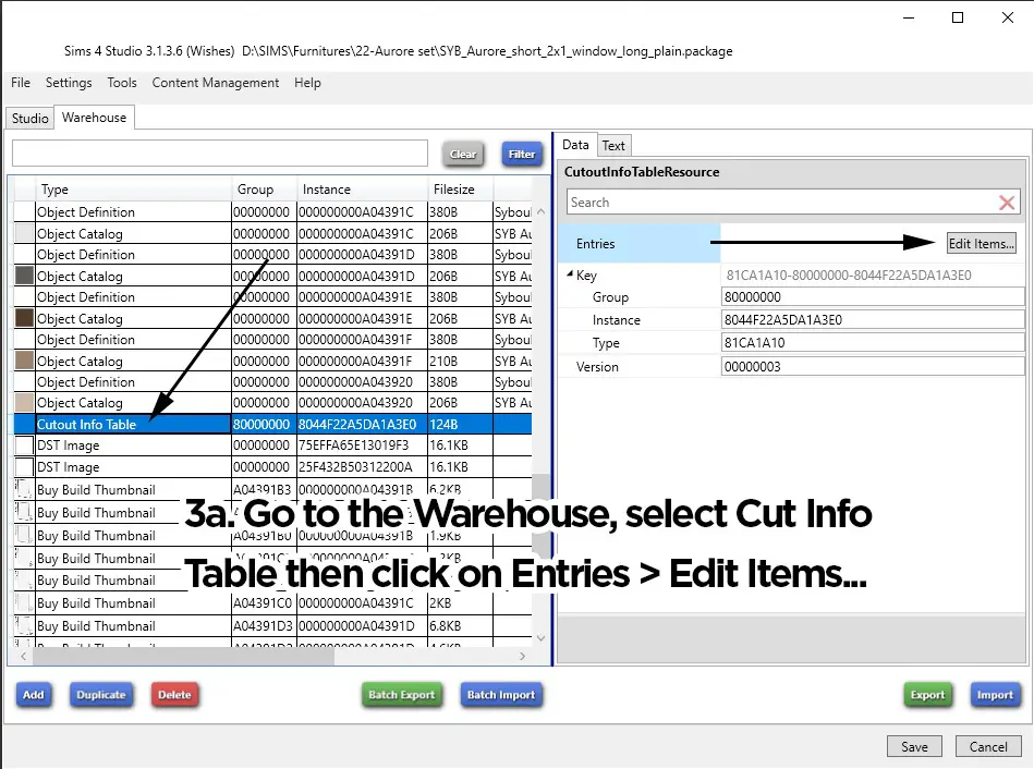
2a. Go to the Warehouse, select Model Cutout then click on Edges > Edit Items…
2b. Erase all but the 4 first edges.
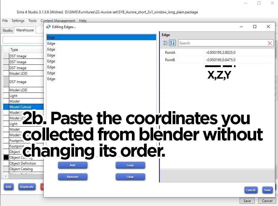
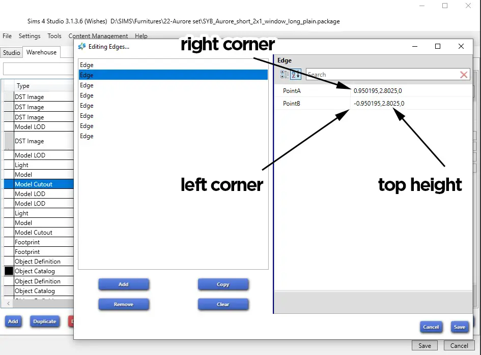
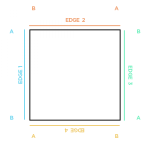
2c. As a reminder, the first 4 edges are the general square shape of our cutout. In your coordinates list, select the higher X and Z and the lower X and Z, and those will be your coordinates. Paste them following this order:
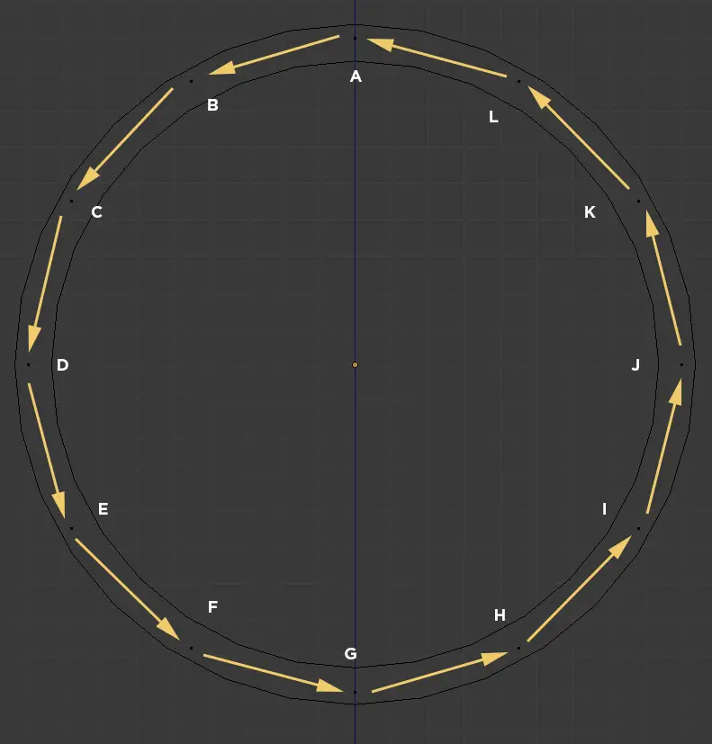
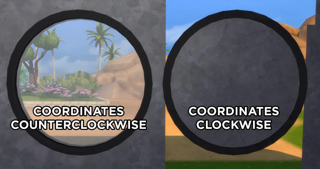
2d. We’ll now need to add the edges from our cutout. Create as many edges as necessary. Place the coordinates between edges counterclockwise.